Engineering design: extending foundation pile supportBlind
in3D Modeling Designheld byMark HenryLast seen:
Contest Ended, Winner(s) have been selected.
-
Open
-
Choosing Finalist
-
Ended
Description:
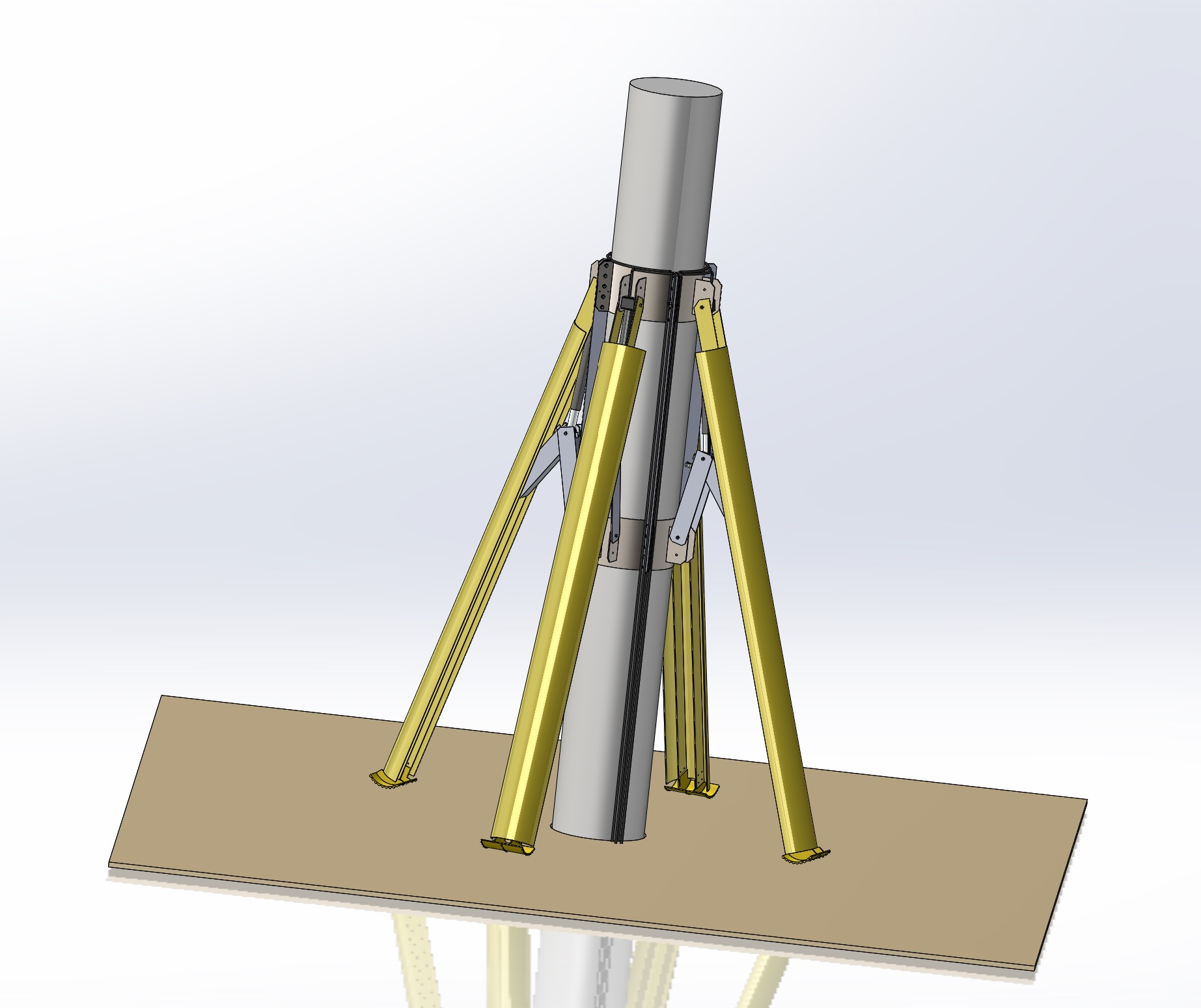
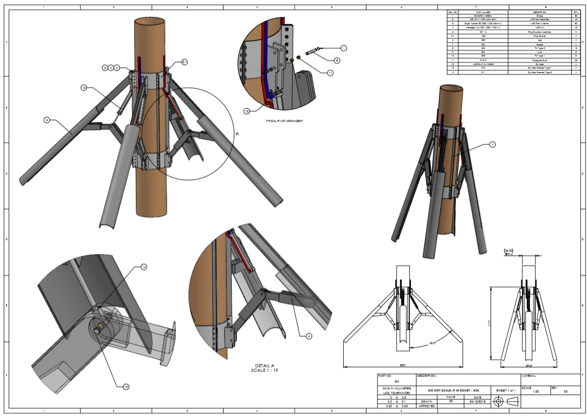
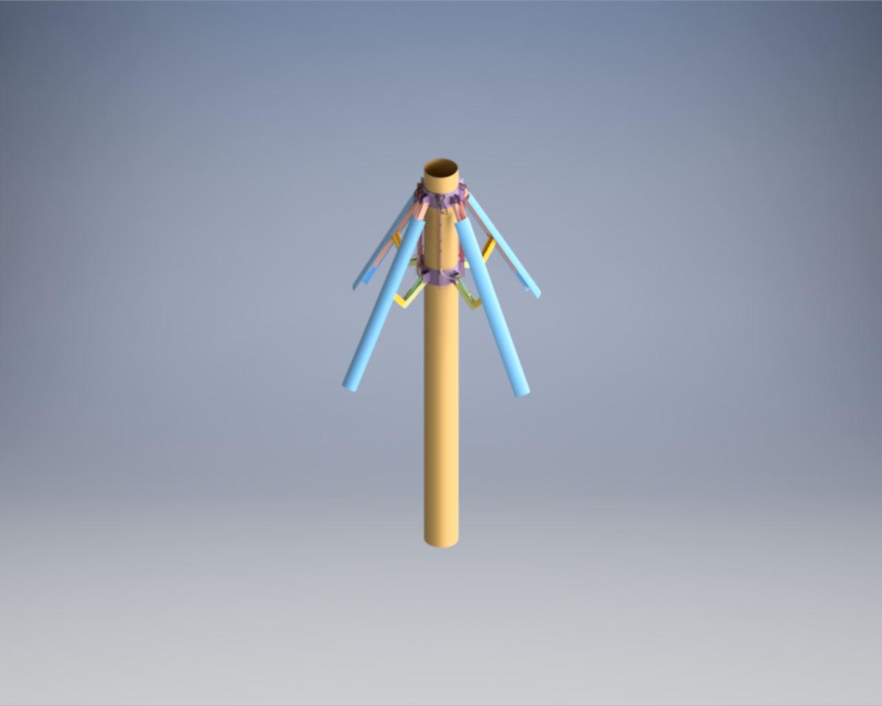
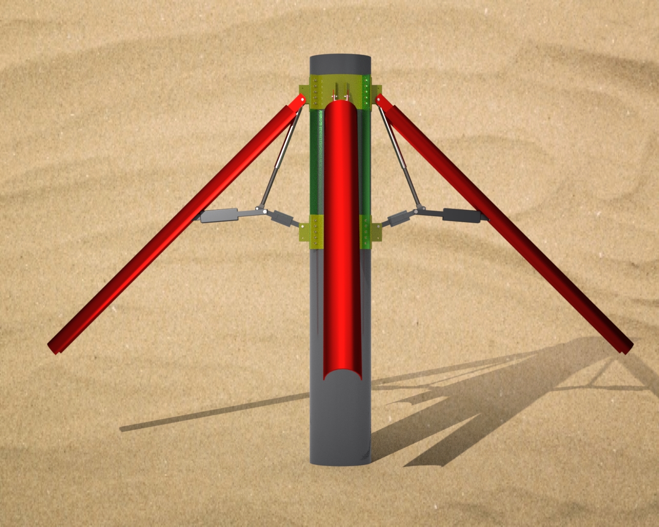
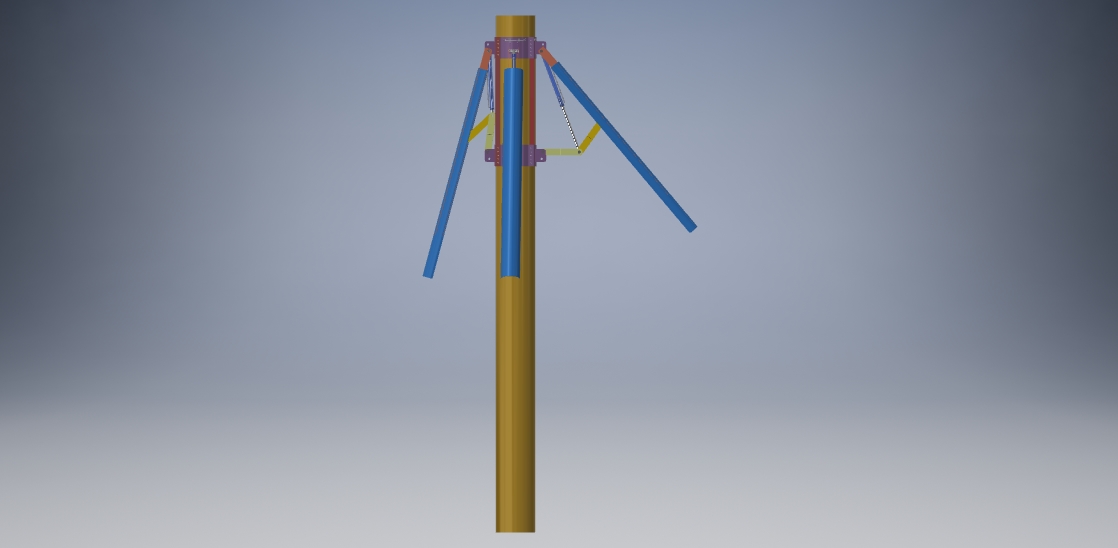
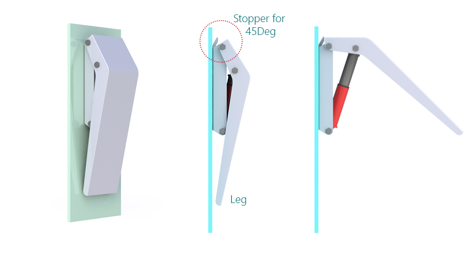
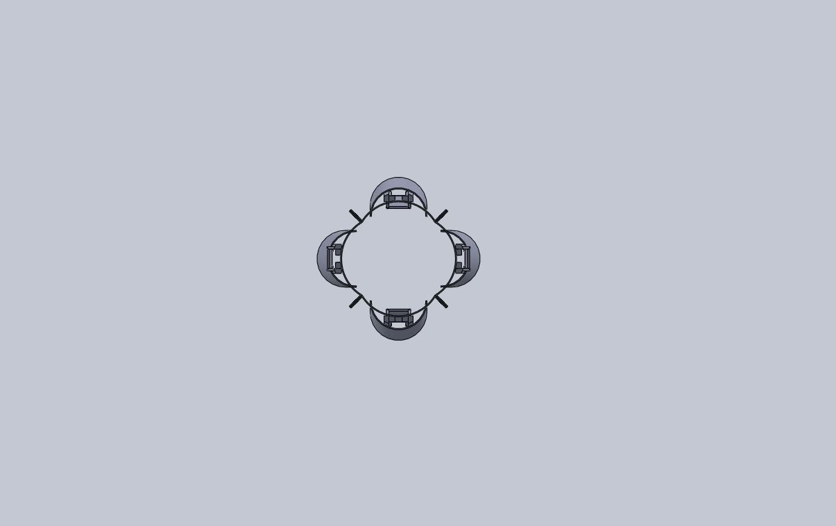
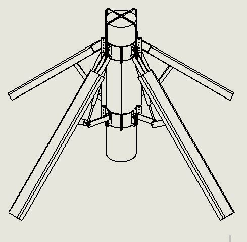
3 different components need to join together to form 1 piece.The combined assembly is a clamp on system, that clamps onto 36" diameter pipe, then when hydraulic pistons are activated the arms extend and lock out to approximately 45deg.
I have attached schematics showing in 2d what I am after. Potential for significant future work for winning designer.
Wants:
Ability to manufacture from Plate steel, bent or welded (no complicated forged pieces). Detailed Bill of Materials. Explosion diagram. Animation showing closed to open sequence. Simplicity to manufacture, elegance of design and arm locking feature when closed and open.If you can show neat hydraulic lines from pistons leading to a single point at top of assembly, that would be a bonus.
The arms when collapsed should be as flush with pipe body as possible.
Moreover this is a qualifier for future work, as we have 4 other project designs needing drawings, and work doing.
Don't Wants:
Complicated pieces, obvious weaknesses.
Software:
- SolidWorks
Additional Information
Now public, as invitation only designers are no longer active.also accept design in 3d autocad, as want to open to more designers.
 Prepaid Prize
Entries


#6Extending Foundation Pile Supportbysimon_d_98
Download Files
- SolidWorks 2017 — Pipe Support GA
- SolidWorks 2017 — 2A-Body-Bore4.00 x
- SolidWorks 2017 — 2A-Rod-Bore4.00-Rod1-STD x
- SolidWorks 2017 — 4.00T2ALY14M13.800 1
- SolidWorks 2017 — 4.00T2ALY14M13.800 2
- SolidWorks 2017 — 4.00T2ALY14M13.800
- SolidWorks 2017 — Arm
- SolidWorks 2017 — Brace
- SolidWorks 2017 — Bush
- SolidWorks 2017 — Clevis
- SolidWorks 2017 — Cylinder Bracket
- SolidWorks 2017 — Cylinder Bracket2
- SolidWorks 2017 — cylinder
- SolidWorks 2017 — GA
- SolidWorks 2017 — Pin
- SolidWorks 2017 — Pin2
- SolidWorks 2017 — Quarter Ring Assembly
- SolidWorks 2017 — Ring Quarter
Dec 31, 2019 10:52
#7extending foundation pile supportbysherifelsheikh
Download Files
- Microsoft Excel 2016 — BOM parts
- Video WMV — Exeploded View
- Video WMV — Pile Foundation Support WMV V9
- Video WMV — Pile Foundation Support-2 WMV V9
- Video WMV — Pile Foundation Support-3 WMV V9
- jpg — Pile Foundation Support V2-1
- jpg — Pile Foundation Support V2-2
- jpg — Pile Foundation Support V2-3
- jpg — Pile Foundation Support V2-4
- jpg — Pile Foundation Support V2-5
- jpg — ARM Assy
- jpg — ARM Assy-2
- jpg — ARM sheet metal base plate
- jpg — ARM sheet metal plate
Dec 31, 2019 20:57


#15Extending Foundation Pile Supportbysimon_d_98

Download Files
- SolidWorks 2017 — GA Draft2
- SolidWorks 2017 — Arm
- SolidWorks 2017 — Cylinder Clevis
- SolidWorks 2017 — Spacer Washer
- SolidWorks 2017 — Pin Type 3
- SolidWorks 2017 — 2A-Body-Bore4.00 x
- SolidWorks 2017 — 2A-Rod-Bore4.00-Rod1-STD x
- SolidWorks 2017 — 4.00T2ALY14M13.800
- SolidWorks 2017 — Brace
- SolidWorks 2017 — Bush
- SolidWorks 2017 — Cylinder Bracket
- SolidWorks 2017 — GA
- SolidWorks 2017 — Leg
- SolidWorks 2017 — Pin
- SolidWorks 2017 — Pin3
- SolidWorks 2017 — Pipe
- SolidWorks 2017 — Quarter Ring Assembly
- SolidWorks 2017 — Ring Quarter
Jan 6, 2020 22:46

#2extending foundation pile supportbyFadi Sayegh

Download Files
- SolidWorks 2019 — Assem foundation pile support
- ImageJ — Capture1
- ImageJ — Capture2
- ImageJ — Capture3
- ImageJ — Capture4
- ImageJ — Capture5
- ImageJ — Capture1.1
- ImageJ — Capture1.2
- ImageJ — Capture1.3
- ImageJ — Capture1.4
- ImageJ — Capture1.5
- video — Assem Hydrolic movement
- video — Assem rotat and exploaded 1 Fadi
Dec 23, 2019 0:36


#3Extending foundation pile supportbysherifelsheikh

Download Files
- Video - WMV — Pile Foundation Support WMV V9
- Video - WMV — Pile Foundation Support-2 WMV V9
- Video - WMV — Pile Foundation Support-3 WMV V9
- jpg — Pile Foundation Support
- jpg — Pile Foundation - Support-
- jpg — Pile Foundation Support-1
- jpg — Pile Foundation Support-2
- jpg — Pile Foundation Support-3
- jpg — Pile Foundation Support-4
Dec 25, 2019 13:47
#5Engineering design: extending foundation pile supportbyFadi Sayegh

Download Files
Dec 29, 2019 16:44


Discussion
Showing last 20 comments -View All
Hi, can you please advise on when a winner will be chosen, or if one as been already.
Thank you
Thank you

Hey Mark, would you rate my design? Thanks
Hi all,
Some really excellent efforts, due to the volume of design entries, and the similarity of many, it will take me a few days to work through all of them based on the original design parameters:
- Similarity to original design brief
——robustnes Functionaility计划环境s, Simplicity of design and ease of construction
- Quality of actual design once uploaded to Solidworks.
The top 5 designers will be invited to future blind design competitions.
Regards, Mark

Can please extend some more days. As i Looked the contest today.
-CS
-CS
Hi coldmonk,
In response to your questions:
1. The device will be fitted prior to driving the pile, so it will expand with hydraulic and driving motion, to the final 45deg expansion shape.
2. It will be retrieved, so the hydraulic pistons will be used to push the pile out at end of life, for re-use. That is the plan anyway :-)
Please feel free to ask any other questions you may have.
I have started the detailed review process and am currently downloading all designs into Solidworks for analysis.
Regards,
Mark
Hey Mark, so from what I've understood this device you're seeking will be used with steel pipe piles, correct?
Regarding this I have two queries viz
1) will the device be installed on the pipe prior to driving the pile or after it has been driven a bit.
2) is the device meant to be used multiple times or is it sacrificial in the sense that concrete will be poured over it as well thus making it a part of the foundation permanently.
I ask these as your request is rather novel.
Thanks
嗨,伙计们,很多问题我会和澄清with answers below:
1. No existing pictures it is a new system and new use. It needs to be run with the legs collapsed against the pile / pipe body. Then while running into place in very soft formation the hydraulic rams will extend the legs out to approximately 45 deg. You have freedom to come up with different hinge and leg extension mechanism, but overall the system must be able to fold flat against body, with total OD less than 60".
2. Loadings for the pile are tricky, installation loadings will have the hydraulic ram apply up to maximum of 10Mt of force on each leg. Service loadings on the system maybe up to 150 - 200 MT Axially through the pile (most of this will be taken through the pile) and 40 - 80 Mt applied laterally to the top of the pile.
3. The legs need to be able to fully collapse for easy of transport and picking up, the total assembly OD should be less than 60".
4. The legs should be able to withstand approx 100 kN m of bending force (the detailed engineering and design of these is not part of this competition)
5. If any one is able to undetake FEA, this would be a big benefit.

Hey Mark. Do you have more photos of the actual clamps on the pipes? Or of the materials being used on an existing system you are using? Just like to get a better idea of what you currently have (if anything?). Thanks - Chris

working on it.

Hi Mark,
I have a doubt about the point E in the part 3 is it able to move up and down if not will not be like top view assemble will be like the design I have sent. please contact me to discuss more. thanks
I have a doubt about the point E in the part 3 is it able to move up and down if not will not be like top view assemble will be like the design I have sent. please contact me to discuss more. thanks
I need to know the application of the pile, so we can make the approximation regarding the lateral forces exerted on the pile, which will be transmitted to the support structure.

upload more illustration, please. I still don't get the idea of what do you want to build.
What's the point of the leg being able to be open-close?
I got that the L length for the curve and the H for the rest as showing in part 1 . is that right ?
Hi mark , The length (L) of the part 3 for just the curve or for all the part ?

hello, is it necessary to make leg curved as shown in aerial view. can i make it straight?

Thanks,cause it was written explosion ,not exploded.
Hi Walxo, exploded view, is a different view of the component schematic, an illustration that shows all parts "exploded" from singular item.
Hi Mark.A few questions.
What that is mean ( Explosion diagram)?Is there any potential explosion risk?Is there any ATEX classification?Is it explosion hatch or not? What is the meaning of the pipe clamp?
What that is mean ( Explosion diagram)?Is there any potential explosion risk?Is there any ATEX classification?Is it explosion hatch or not? What is the meaning of the pipe clamp?
Hi guys, thanks for taking time to look at this.
I will pre-pay and add a 2nd prize as well.
"3 parts" was just referencing trying to reduce different parts, to try and stadardise for simplicity. If there are more parts, but the design is better / simpler then that will be a good solution too.
Mitch, in response to your questions:
- This structure is to stabilise the pile as it is taking lateral loadings in shallow and weak soil conditions.
- the pile will be installed by crane
- The pipe within this device is the structural pile, it will be jetted into place or possibly installed in a predrilled hole and cemented.
Regards, Mark
Similar Contests on Cad Crowd
Angled Keyboard Slide
The design requires a clean simple method with minimized parts and manufacturing costs. Product is low volume, 250 to 500 pieces per year. We are interested in minimizing capital tooling costs. Design challenge is to design a keyboard slide platform that sits at a 32.5 degree angle (see attached documents). Keyboard slide needs to easily lock in upward position when not in use, and needs to easily be released and slide downward when in use. The keyboard slide is on a cart platform, so when the cart is being moved around, if it gets bumped, we do not want the keyboard slide to dislodge and slip into the down position.
Medical Bin & Cover Re-design
Redesign of our medical storage bins and cover access methods. The overall industrial and mechanical design initiative should explore new methods and ways to reduce lid opening space. (See attached document for full details.)
Survival gear/Knife design
Working on a survival oriented product, Looking for a professional preferably with experience in the niche to finalize a design and make realistic HQ renderings of the finished product/product parts.
Premium Headphone Design
We want a premium vintage design for our new product line. It represents, vintage, traditional, formal style, high-tech, metal finish for day to day rugged use. Type: Over-ear Bluetooth Premium Headphone Target Audience: 20- 50 year olds Competitors: Bose, Sennheiser, JBL, KEF, Marshall Kilburn Design: 90° swivel earcups, extendable, foldable headphone Material: Leather headband, metal earcups (Partially plastic is also welcome) Specification Details: Driver Unit: 40mm / 50mm Bluetooth and 3.5mm plug LED Indicators to show battery, Power button with light indicators, Volume button/s (But not limited to your design, please feel free to be creative) Any software is acceptable, if STL format file can be provided. Any further questions, please feel free to comment.
Bas Relief Panels
Create bas relief panel models to be CNC routed from MDF sheet. I will provide exact panel dimensions, sketches of the design and images to be modeled. Photos of similar examples attached.
ZM Designs
Designer